
Today, I will demonstrate how to set up an IPSEC SITE-TO-SITE VPN configuration using the PFSense Firewall. For this purpose, I’ve established an internal environment to simulate all configurations, hence all the IP addresses mentioned below are fictional.
To illustrate the scenario, we have a simple topology explaining how our environment is configured, where there is one PFSense edge device on each side, each with its respective LAN and WAN IPs.

By analogy, consider that OFFICE A is physically located in São Paulo and OFFICE B in Rio de Janeiro. Without some form of VPN connection, L2L, or MPLS, for instance, communication between the LAN networks would be impossible. In our case, we will utilize a VPN tunnel.
The first step in the configuration process is to navigate to the VPN > IPSEC tab as shown below.

Upon entering the configuration screen, we will begin configuring phase 1 of the VPN tunnel. Phase 1 essentially involves setting up WAN x WAN on each side, and phase 2 involves LAN x LAN on both sides of the local network. To start, click on the “+” icon.

Now, as previously explained, we will initiate the configuration of phase 1. To do this, you need to perform the configurations as shown below.
- Key Exchange version: V2 – We use version 2 because it is more secure compared to version 1 and brings more stability to the VPN tunnel.
- Internet Protocol: IPv4 – We are using the standard IPv4.
- Interface: WAN – By default, if you have only one internet link, you should choose the WAN interface. However, if you have more than one link, select the interface you wish to use for the tunnel.
- Remote Gateway: Here, you will insert the remote side’s WAN IP address.
- Description: You may enter a description of your choice.
- Authentication Mode: Mutual PSK – We will use a shared password for establishing the tunnel. The same password must be entered on both sides of the PFSense. It’s possible to achieve the same configuration using a digital certificate, which I will demonstrate in a future post.
- My Identifier and Peer Identifier will not be changed.
- Pre-Shared-Key: Enter a shared password that must be the same on both PFSenses.

- Encryption algorithm: AES 256 bits – I chose this algorithm for being one of the most secure available.
- Hash algorithm: SHA1 – Chosen for the same reason as the previous option.
- DH key group: I used a 2048 bits key for the minimum desirable security.
The rest of the options do not need to be changed. I will utilize them in future posts.

After completing all the configurations shown, simply save and apply the settings. Now we will proceed to configure phase 2, for this, click on the “+” under the “IKE” option then click on the “+” that appears.

At this stage, we will only input the remote side’s LAN network and enter a description.

For the second part, simply change the value of the PFS key group to 2048 bits. The remaining options do not need to be altered.

Now we have both phases configured. Just remember to activate the IPSEC service.

The same configurations demonstrated above must be set up on the other PFSense, with the only changes being the WAN address for phase 1 and the network address for phase 2. This should be configured as shown in the image below.

Now that you have both sides of the tunnel configured, let’s establish the connection between them. To do this, simply follow the path STATUS > IPSEC.

Now, you just need to click on the “play” icon.

Done. Our VPN has been successfully connected to the remote side.

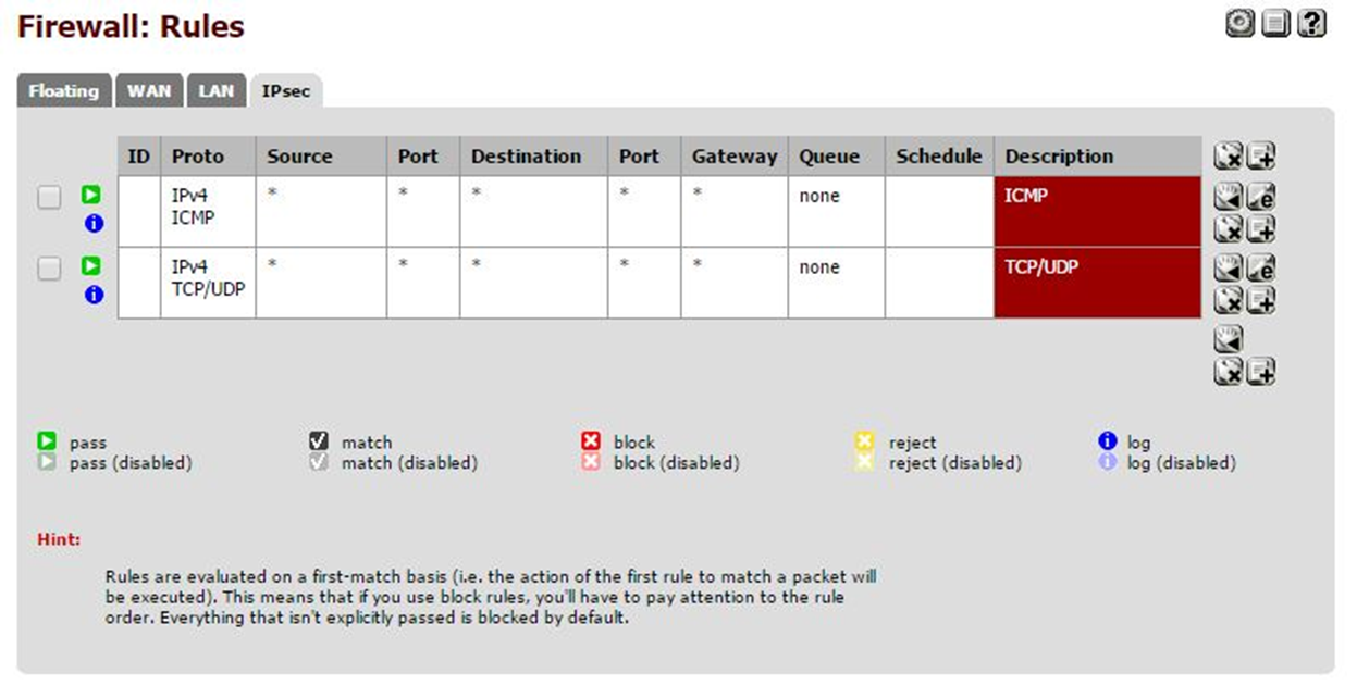
Before testing, let’s just allow communication between the two sides by accessing FIREWALL > RULES > IPSEC.

Now the configuration will vary according to each one’s needs. You can either create a rule for any:any or be more conservative and configure only the rules you need. To start, simply click on the “+”.

As I mentioned earlier, I opted for the more conservative approach and only allowed ICMP (ping) and TCP/UDP protocols. With these two protocols allowed, I ensure minimal desired communication between the sides.
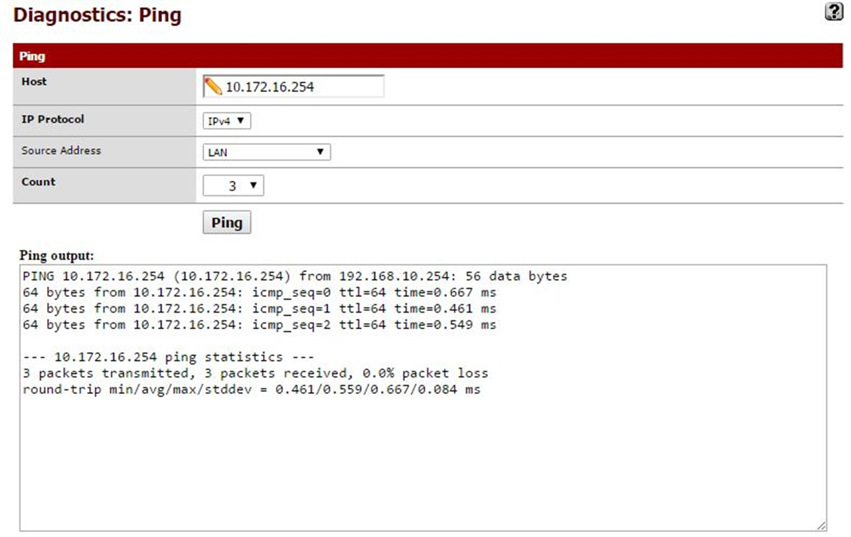
Let’s move on to testing. The first test is the famous Ping, which is used solely to test connectivity between the sides, nothing more than that.
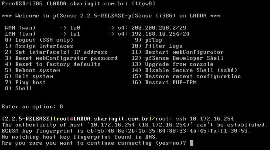
The second test is an SSH connection from one host to another. From HOST A, I communicated with HOST B using its LAN address, meaning LAN to LAN are “talking.”
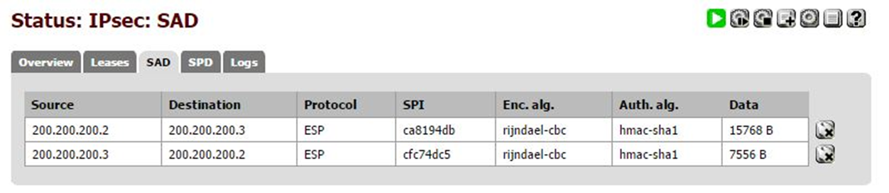
The final test involves checking the amount of data traffic under the “Data” tab. If it is different from 0, it means that there is indeed traffic within our IPSEC tunnel.
The tunnel has been successfully configured and tested. In some cases, depending on the number of hops in your network, it may be necessary to create static routes to reach the remote host. However, this varies from firewall to firewall.


Leave a Reply